
FAQS
What Is an RF Power Amplifier?
An RF Power Amplifier (RF PA) increases the power of a radio-frequency signal before it reaches an antenna. In a phone, base station, radar, or satellite terminal, it helps a transmitted signal travel through real-world space. The task sounds simple. The engineering is not. A PA must deliver useful output while managing heat, battery use, signal distortion, and interference with nearby channels.
The demand for reliable radio links continues to grow. Ericsson’s June 2024 Mobility Report projected 5.6 billion 5G subscriptions worldwide by the end of 2029. The GSMA’s 2024 Mobile Economy report estimated that mobile technologies and services contributed $5.7 trillion to global GDP in 2023. These figures describe the wider communications ecosystem, not the RF amplifier market itself. Still, they show why efficient radio hardware matters. A tiny component can affect device runtime, network coverage, and the quality of a transmitted signal.
This guide explains what an RF Power Amplifier does, how it works, and where engineers use it. It also introduces key measures such as gain, output power, efficiency, and linearity. Consider a handset sending data from a crowded street: the amplifier must strengthen the signal without wasting excessive battery energy or corrupting it. That example is useful, but incomplete. Real designs involve trade-offs, and no single amplifier suits every frequency band or application. Understanding those trade-offs makes specifications easier to judge.
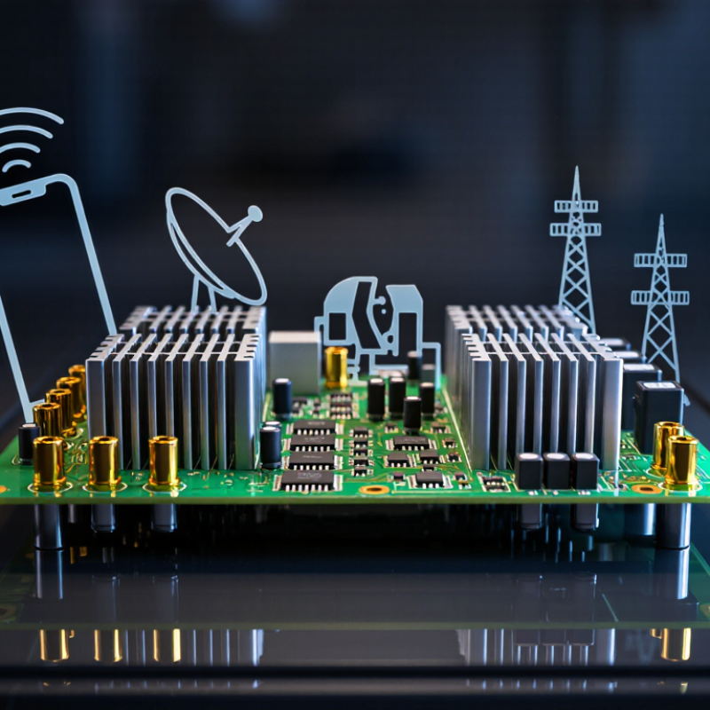
Definition and Purpose of an RF Power Amplifier
An RF power amplifier, or PA, raises the power of a radio-frequency signal so it can drive an antenna or another load. It usually sits near the end of a transmitter chain, after stages that generate and shape the signal. The PA increases the signal’s usable output level; it does not create the information being transmitted. That distinction matters. Its energy comes from a DC power supply, and some becomes heat rather than RF output.
Consider a transmitter feeding an antenna through a short coaxial cable. The PA must provide enough power for the intended range while keeping the signal within acceptable distortion limits. Engineers assess output power, gain, efficiency, operating frequency, and thermal behavior. These figures describe different things, so a high gain number alone does not guarantee a suitable amplifier. In real designs, load matching and cooling also affect performance. A warm heatsink is a visible reminder that efficiency is never perfect. I find it easy to blur gain and output power when reading specifications, so checking the units is worthwhile. A design that works on paper may still need careful testing under its actual load.
What Is an RF Power Amplifier? — Definition and Purpose of an RF Power Amplifier
| Dimension | Definition or Function | Practical Details |
|---|---|---|
| Definition | An RF power amplifier (RF PA) is an electronic circuit that increases the power of a radio-frequency signal. | It is commonly the final amplification stage in a transmitter, positioned before the antenna or another RF load. |
| Primary purpose | It supplies enough RF power for a signal to be transmitted through an antenna or delivered to a specified load. | The required output depends on the communication distance, antenna system, operating regulations, and application. |
| How it amplifies | A small RF input controls energy drawn from a DC power supply, producing a higher-power RF output at the same intended signal frequency. | A PA increases signal power; it does not create information that was absent from the input signal. |
| Frequency range | RF power amplifiers are designed for particular frequency bands, from radio frequencies through microwave frequencies. | There is no single frequency range for all PAs. The circuit, matching network, and components must suit the intended band. |
| Power gain | Power gain describes how much the amplifier increases signal power, usually expressed in decibels (dB). | Gain is the ratio of output power to input power. It is distinct from output power, which is commonly specified in watts or dBm. |
| Output power | Output power indicates the RF power delivered by the amplifier under stated operating conditions. | For reference, 1 W is 30 dBm and 10 W is 40 dBm. Actual ratings depend on frequency, signal type, temperature, and load conditions. |
| Efficiency | Efficiency indicates how effectively the amplifier converts DC input power into RF output power. | Some DC energy becomes heat. Higher efficiency can reduce power consumption and cooling requirements, but may involve trade-offs with linearity. |
| Linearity | Linearity describes how accurately the amplifier reproduces changes in the input signal without unwanted distortion. | It is especially important for modulated signals with varying amplitude. Excessive distortion can cause spectral spreading and interfere with adjacent channels. |
| Operating class | Amplifier classes describe the operating behavior and conduction of the active device. | Class A and Class AB are used where linearity is important; Class C and switching or tuned classes can offer higher efficiency in suitable applications. |
| Impedance matching | Matching networks help transfer RF power between the amplifier, transmission line, and load. | Many RF systems use a nominal 50-ohm interface, but the required impedance depends on the system and amplifier design. |
| Typical applications | RF PAs are used wherever a radio-frequency signal must be transmitted or delivered at a higher power level. | Applications include wireless communications, broadcast transmitters, radar, satellite links, and RF test equipment. |
| Key design considerations | Selection involves balancing output power, gain, efficiency, linearity, bandwidth, and reliability. | Thermal management, load conditions, filtering, and applicable transmission limits should also be considered. |
Specifications vary by design; compare amplifier performance under the same frequency, signal, and load conditions.
How an RF Power Amplifier Works
An RF power amplifier (PA) raises a radio-frequency signal before it reaches an antenna. A transmitter feeds it a carefully shaped signal carrying voice or data. Inside the PA, transistor devices use energy from a DC supply to create a stronger RF output. Matching networks help transfer that energy between circuit stages and the antenna. That is not magic. It is controlled energy conversion, with trade-offs.
The output must stay clean enough to preserve the signal’s information. Push a transistor too hard and it can distort the waveform, create unwanted harmonics, and waste more power as heat. Heat matters. Engineers adjust bias and use linearization techniques to balance output, efficiency, and signal quality. A useful simplification, though: real designs vary by frequency band, waveform, and device. The 3GPP NR specifications include a common handset transmit-power class of 23 dBm, about 200 milliwatts. Meanwhile, the GSMA’s Mobile Economy 2024 report projects 5.5 billion 5G connections by 2030, underscoring why efficient radio transmission matters. That figure is a forecast, not a guarantee.
Key Components and Amplifier Classes
An RF power amplifier raises a low-level radio-frequency signal before it reaches an antenna. Its job is to deliver useful transmit power without distorting the information carried by the signal. A practical amplifier includes a power transistor, input and output matching networks, bias circuitry, and a path to remove heat. The matching networks help transfer energy between circuit stages; poor matching can waste power or strain components. Heat matters. GSMA’s 2024 Mobile Economy report forecasts 5.5 billion 5G connections worldwide by 2030. That growth increases pressure for compact, efficient radio hardware, though connection forecasts alone do not predict amplifier sales.
Amplifier classes describe how devices conduct during each signal cycle. Class A conducts throughout the cycle and offers good linearity, but wastes substantial power as heat. Class AB conducts for more than half a cycle, balancing linearity and efficiency in many radio designs. Class C conducts for less than half a cycle and can be efficient, but its distortion limits use with many complex signals. Class E and F use tuned networks and switching behavior to improve efficiency at selected frequencies. Not a free gain. Designers still manage bandwidth, heat, signal quality, and load changes. Doherty architectures can improve efficiency when output power backs off, but add circuit complexity. The best choice depends on the waveform and operating conditions, not a class label alone.
Performance Metrics and Operating Characteristics
An RF power amplifier raises a radio-frequency signal to a level suitable for transmission. Its gain describes how much the input signal increases, but gain alone says little about usable performance. Output power and the 1 dB compression point show how strongly the amplifier can drive a load before its response becomes noticeably nonlinear. Engineers measure these values at a stated frequency, supply voltage, and load impedance. Change one condition, and the result may change. Heat matters.
Efficiency indicates how much DC supply power becomes useful RF output. Power-added efficiency also accounts for the signal power entering the amplifier, making it useful when comparing designs. Linearity matters when a signal carries complex modulation: excessive distortion can worsen error vector magnitude and create unwanted spectral regrowth. A bench test might reveal clean output at moderate power, then a sharp rise in distortion near the amplifier’s limit. That boundary is easy to underestimate.
Operating class, bias, matching networks, and cooling all shape real-world behavior. A design optimized for high efficiency may sacrifice linearity, while a more linear operating point can produce extra heat. Stability across the intended frequency range also deserves attention, especially when the antenna load changes. Results from a fixed laboratory load are helpful, but they do not capture every field condition. There is no single metric that tells the whole story.
What Is an RF Power Amplifier? — Performance Metrics and Operating Characteristics
This representative curve shows power-added efficiency (PAE) rising as RF output power increases, then falling near the amplifier’s upper operating range. Higher output levels can improve efficiency but may increase gain compression and distortion. Actual performance depends on amplifier design, frequency, and operating conditions; these values are illustrative, not specifications for a particular device.
Common Applications and Design Considerations
What Is an RF Power Amplifier?
Common Applications and Design Considerations
An RF power amplifier raises a radio-frequency signal to a level suitable for transmission. It is used in wireless infrastructure, satellite links, radar equipment, and test systems. In a cellular base station, the amplifier must deliver steady power as traffic loads change. Small distortions matter. Engineers weigh output power, gain, bandwidth, linearity, and efficiency together, since improving one can compromise another. A highly efficient design may distort more near its power limit. Heat builds up in compact enclosures, so thermal paths and airflow need attention early.
Tips: Match the amplifier to the signal’s frequency range and required output power, not just its peak rating. Leave headroom for modulation peaks. Test it with the intended waveform and load; bench results can look better than field performance. Keep RF traces short, use controlled impedance, and place decoupling components near supply pins. Check stability under different operating conditions. Cable loss is easy to overlook.
Designers also consider impedance matching, noise, supply variation, and electromagnetic coupling. A mismatch can reflect power toward the amplifier and increase stress. Filters may reduce unwanted emissions, but they add loss and need careful placement. Enclosures, connectors, and grounding can all change measured results. A tidy schematic is not the whole design. Testing prototypes across temperatures and loads helps reveal weak points before deployment. Some trade-offs remain imperfect; recording them can make future maintenance more predictable.
Skip to content
